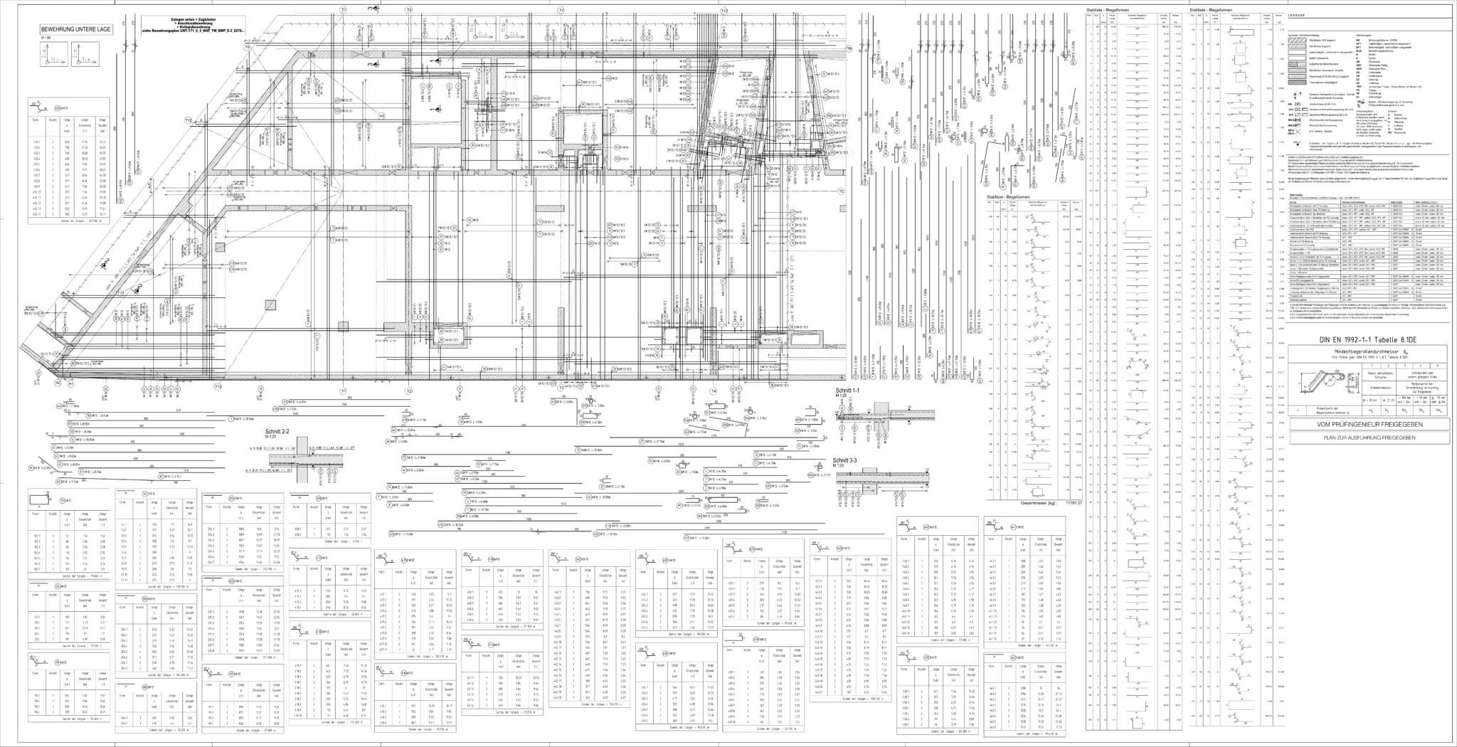
An armored drawing is the basis for the correct execution of reinforcement of building elements in accordance with construction requirements and building regulations in order to ensure the load-bearing capacity, stability and durability of the structure.
It has the task of describing the location, cross-section, quality, length and number of steel inserts to be installed in reinforced concrete elements, in accordance with the guidelines for reinforcement,
It provides information for the contracting company regarding the assembly of reinforcing bars in reinforced concrete elements.
This ensures that the building is safe and stable, and individual elements can withstand greater loads. This is due to the fact that reinforced concrete has higher tensile strength when bending than pure concrete.
Reinforcement plans must be prepared and checked by a qualified construction engineer to ensure their compliance with static calculations of the building and local building standards and regulations.
How we work:
We make drawings based on the provided static calculations and formwork plans (2D or building model in the form of ifc files (BIM) or tbw (Allplan).
Before starting the project, we determine the style and standard of drawings, the required level of detail and the applicable deadlines.
Each of our drawings is verified in accordance with the quality policy adopted in our company.
Completed drawings are delivered in the selected format, e.g. pdf, dwg or tbw files (Allplan).
For each plan, we can, at the request, prepare an external list of steel in A4 format and generate files in abs format for automation of production of reinforcing bars.